
ICCP SYSTEM WILSON WALTON KOREA Japanese The ICCP system comprises Anodes, Reference electrodes and a Transformer/Rectifier controller power unit and is designed to maintain automatic control of the optimum output current by means of reference electrodes. he sizes of the components and their positions on the hull are specified according to design parameters which take into consideration the size of the vessel and fluctuations in the protection current likely to be encountered during seagoing service. Whilst the foregoing protects the hull structure, it is also important to protect the propeller, exposed shafting and rudder. The propeller and shafting are qrounded to the hull structure with a shaft slipring, making them electrically common with the hull. The rudder is also grounded with a flexible cable mounted on the rudder stock and, with electrical continuity established, the ICCP system fully protects the components against corrosion. POWER CONTROLLER UNIT 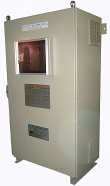 Power Controller Unit incorporates a microprocessor which carries out automatic self checking, continually monitors all readings received and indicates operational errors for the ship's personnel. Data received can also be stored for output later onto computers or hard copy log sheets. There is also a built-in facility for connecting the system directly to the ship's computer or into a separate data logger/chart recorder. Our ICCP systems can be provided for any size of vessel. A new design is now available for small, specialized craft, such astugs,fishing boats, supply boats, ice breakers and FPSO, whose cathodic protection requirements can be more demanding and require specialized system. In icebreakers, for example, exposed galvanic anodes on surface of the hull would be extremely vulnerable to damage or loss, particularly in the bow section. Coatings on icebreakers are also quickly damaged, exposing large areas of bare steel which require high current densities for adequate protection. Our specifically designed impressed current systems can meet these demands. In FPSO, for another example, which require very high grade system and longer lifetime as 20 ~ 25 years. 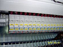 Specification Power Source : AC220 1P or AC440 1P/3P or AC690V 3P or Customer's specification Capacity of Rectifier : 100 ~ 800 Amp, 12 ~ 24VDC Anode number per PSU : 18 ea Max. Reference electrode number per PSU : 6 ea Max. IP Grade : IP23 or IP44 A LCD display is provided enabling the vessl's personnel to record readings on a reqular basis, entering themonto a log sheet which is returned to our office. Anu adjustments needed are made by our fiield engineer or ship¡¯s crew. There is a built-in facility for connecting the system directly to the ships computer system or intoseparate data logger.Full electrical protection is provided on input whilst output fuse are fitted in each anode circuit. All components are readily accessible within the drip-proof steel enclosure. REMOTE DISPLAY UNIT 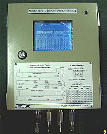 Remote Display Unit provide a large size graphic LCD which anable the ship's engineer to check easily all recordings wirhout scroll of display. further it provide a mimic board so that they can find out easily each location of anodes and reference electrode. Main Feature Display of hull potential for every reference electrode Display of current output for every anode Display of total current output for each power control unit Display of temperature for each power control unit Display of abnormal alarm for each power control unit ; - overprotection - under protection - over current - high temperature - power fail Output contact for abnormal alarm Data interfacing with computer based ship's alarm monitoring system.
FEATURE: 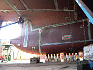 Fully split, underwater replaceable within 1 or 2hours. Robust construction yet extremely compact sized for massive external impact. Simplified installation procedures reduce costs of anode replacement inthe water. innovative sealing system ensures the perfect water tight. Semi-permanent life time of anodes Ensures damage tree against large pressure fluctuation(8-15Kpa) Shop Test Pressure:tested up to 10 bars air,(Normal anode test pressure:1.2bars) APPLICATION: 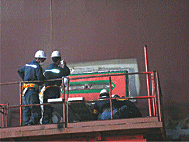 LARGE CONTAINER VESSEL LNG SHIP ICE BREAKER FPSO NAVAL VESSEL FISHING VESSEL PRODUCT CARRIER BULK CARRIER OFFSHORE PLANT After extensive research and development, we have designed the new generation ICCP anode to cope with any calculated pressure fluctuation on ship's stern area. For each individual speed and power we can calculate these pressure fluctuation. Recently the size of container ships has increased, however the draft of such large ships remains the same(12.5 - 13.5). Accordingly this will increase the load of propeller blade as well as the amplitude of pressure fluctuation to the stern anode positioned area. The bilge vortex of such large container ship is extremely stronger and it's trace line is more likely closer to the stern anode and this may hit the surface mounted linear anode.(after anode) In addition, due to the continuous, regular pressure fluctuation and the effect caused by bilge vortex, the anode body made by epoxy resin will be easily damaged and holding nuts of anode may easily loosen and we therefore predict some hair cracks to the cable. So, the sea water may be sucked into the ship's inside and sometime lost the anode totally. ITTC(International Towing Tank Conference) (1)has recommended around 8kpa as a maximum pressure fluctuation but some model tests of 6000 Teu container ships shows it's value appx 11kpa or more. The newly constructed anode is very strong and compact and is guarantied sea water leak proof even if pressure fluctuation around 8-15kpa or more. We recommend that the specially designed with steel plate back up, under water replaceable anode is to be fitted so that the anode can be replaced anytime without dry docking. 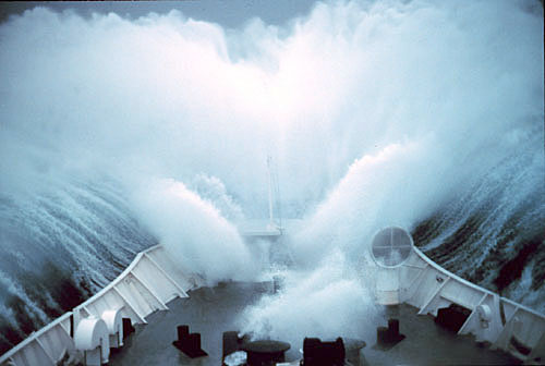  |